


Views: 274 Author: Otechkabel Publish Time: 2026-08-28 Origin: Site


Content Menu
● What Is an E-Marker Chip in a USB-C Cable?
● How Does an E-Marker Chip Work?
>> What an E-Marker Cannot Do Alone
● When Do You Need an E-Marker Cable?
>> 5A and 100W USB-C Charging Cables
>> USB PD 3.1 and 240W Charging Cables
>> High-Speed Data and USB4 Cables
● E-Marker Cable vs. Standard USB-C Cable
● How to Specify an E-Marker USB-C Cable
>> 2. Define Power, Data, and Video Separately
>> 3. Confirm the Entire Cable Assembly
● Common E-Marker Misconceptions
>> Every USB-C Cable Needs an E-Marker
>> An E-Marker Cable Always Supports Video
>> A 240W Cable Charges Every Device at 240W
>> An E-Marker Chip Guarantees a Safe Cable
>> An E-Marker Chip Guarantees a Safe Cabl
>> All USB-C Cables With the Same Wattage Are the Same
● Building a Clear USB-C Product Range
● FAQ
>> What is an E-Marker chip in a USB-C cable?
>> Do I need an E-Marker cable for a 65W laptop?
>> Is every 100W USB-C cable equipped with an E-Marker?
>> Does an E-Marker cable always support fast data transfer?
>> Does an E-Marker cable guarantee video output?
>> Can a 240W USB-C cable charge lower-power devices?
>> How can I choose the right E-Marker cable for my product?
A USB-C E-Marker chip is a compact electronic component built into a USB-C cable connector. Its job is to identify the cable's power, current, data, and functional capabilities to connected devices.
For a basic phone-charging cable, an E-Marker may not be necessary. For higher-power laptop charging, 240W USB-C charging, high-speed storage, docking stations, and professional display applications, it can be an essential part of a reliable cable design.
For cable brands, wholesalers, and device manufacturers, understanding E-Marker technology helps prevent unclear specifications, compatibility issues, and misleading product claims.
E-Marker stands for Electronically Marked Cable. It is an integrated circuit placed inside one or both connectors of a USB-C cable.
When a charger, laptop, docking station, monitor, phone, or other USB-C device is connected, the device can communicate with the cable's E-Marker. The chip reports the cable's designed capability before higher-power or higher-performance operation is enabled.
Depending on the cable type, an E-Marker may identify:
- Maximum current capability, such as 3A or 5A
- Supported charging power range
- Voltage capability
- Passive or active cable design
- Data-transfer capability
- Cable length and signal-related characteristics
- USB4 or other advanced cable characteristics
- Manufacturer and product identification information
The key point is simple: a USB-C connector shape does not tell users everything about a cable.
Two USB-C to USB-C cables can look almost identical. One may only support 60W charging and USB 2.0 data. Another may support 240W charging, high-speed data transfer, or advanced docking applications. The E-Marker helps the connected devices recognize the difference.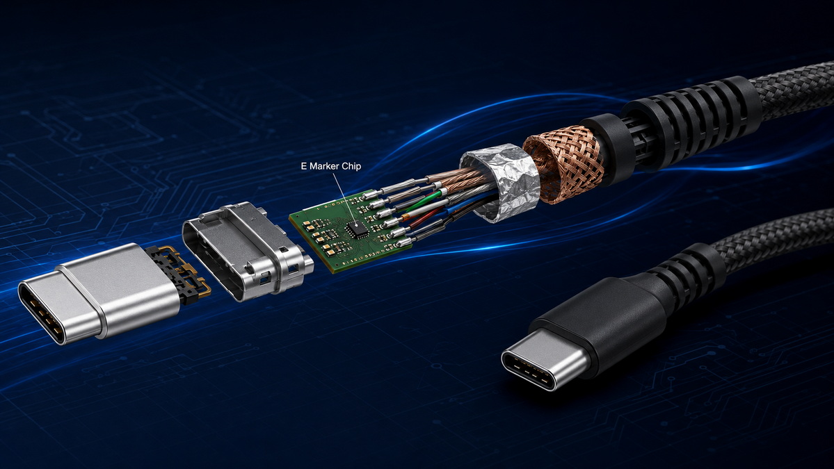
A USB-C connection begins with communication between the connected devices. In an applicable cable design, one device provides VCONN power through the USB-C connector to operate the cable's internal electronics.
The E-Marker chip then communicates the cable's declared characteristics. This helps the system determine whether the cable can support the requested power level or data mode.
For example, imagine a laptop connected to a high-power USB-C charger:
1. The charger, laptop, and cable establish a connection.
2. The system identifies the cable's capability.
3. The cable reports whether it supports 3A, 5A, or an Extended Power Range design.
4. The charger and laptop negotiate an appropriate charging profile.
5. The delivered power remains limited by the capability of the charger, cable, and device.
This process helps prevent a charger from assuming that every USB-C cable can safely carry the same current.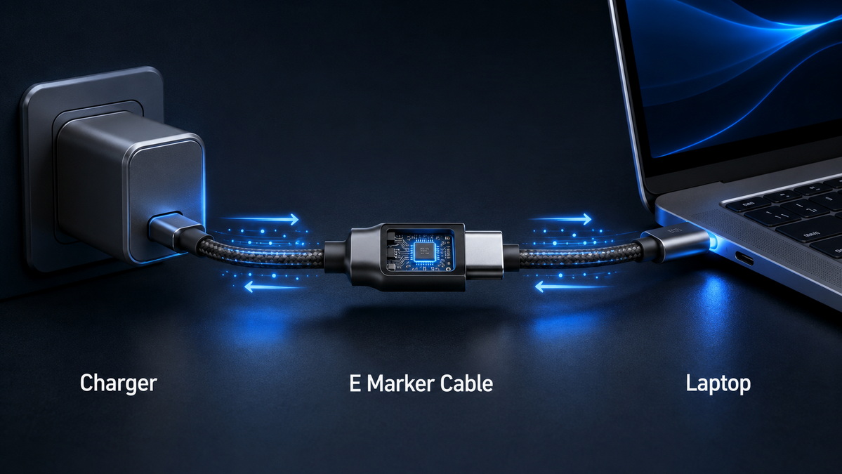
An E-Marker can help connected devices:
- Identify whether a cable supports 5A current.
- Recognize a cable designed for higher-power USB-C charging.
- Distinguish between certain passive and active cable designs.
- Communicate information relevant to advanced data applications.
- Support controlled power negotiation in compatible USB-C systems.
An E-Marker is important, but it is not a complete quality guarantee.
It cannot independently ensure:
- Correct wire gauge and conductor quality.
- Low voltage drop over the required cable length.
- Stable high-speed data transmission.
- Video compatibility with every USB-C device.
- Reliable connector soldering and strain relief.
- Proper shielding and electromagnetic performance.
- Honest product labeling.
- Overall safety and durability.
A dependable USB-C cable requires the right chip, conductor structure, connector design, shielding, materials, assembly process, and quality-control process.
An E-Marker cable is most important when a USB-C application requires higher current, higher charging power, faster data, or a more advanced cable construction.
Standard USB-C cables commonly support up to 3A current. At 20V and 3A, this provides up to 60W of charging power.
When a cable is designed to carry 5A, it needs an E-Marker to identify that higher-current capability. At 20V and 5A, the cable can support up to 100W in an appropriate charging system.
This makes E-Marker-equipped 5A cables suitable for many laptop charging applications, including devices that require:
- 65W charging
- 87W charging
- 90W charging
- 96W charging
- 100W charging
A 3A cable may still charge a 65W laptop, but it can limit the available charging power. The device may charge more slowly, maintain battery level only under heavy use, or display a low-power charging notification.
USB-C charging can now reach up to 240W in systems designed for USB Power Delivery 3.1 Extended Power Range.
These higher-power cable designs use a maximum current of 5A while supporting higher voltage profiles. They are used in certain high-power laptops, workstations, gaming devices, displays, and other equipment that can benefit from a single USB-C power connection.
A 240W cable should be clearly designed and tested for the intended application. The product specification should state the power rating, supported voltage range, cable length, and charging protocol compatibility.
A cable labeled "240W" does not automatically mean that every device will receive 240W. Actual charging power is determined by the lowest supported capability among:
- The USB-C charger
- The USB-C cable
- The connected device
- The supported power-delivery profile
- The operating conditions of the system
USB-C cables can support very different data-transfer speeds. Some are designed only for USB 2.0 data transfer at up to 480 Mbps. Others are built for 5Gbps, 10Gbps, 20Gbps, or USB4 performance.
Higher-speed cable designs require more demanding signal performance. They may use carefully selected conductors, shielding, twisted-pair structures, impedance control, and advanced connector construction. In relevant designs, E-Marker technology provides the connected devices with cable identification information.
High-speed E-Marker cable applications may include:
- External solid-state drives
- USB-C docking stations
- USB4 accessories
- High-resolution display adapters
- Capture devices
- Professional cameras
- Industrial equipment
- Data-intensive mobile workstations
A passive cable relies primarily on its physical conductor design. An active cable includes additional electronics to support signal transmission over longer distances or at more demanding data rates.
Active USB-C cables commonly need electronic identification because their internal circuitry plays a direct role in data transmission and cable operation.
For longer high-speed projects, cable length should always be specified early. A 0.5-meter cable and a 2-meter cable may require very different design solutions, even when the connectors and advertised data speed appear similar.
| Feature | Standard USB-C Cable | E-Marker USB-C Cable |
|---|---|---|
| Typical current capability | Up to 3A | Often 5A, depending on cable design |
| Typical charging capability | Up to 60W at 20V/3A | Up to 100W or 240W, depending on design |
| Data capability | Often USB 2.0, but varies by construction | Can range from USB 2.0 to USB4, depending on design |
| Suitable applications | Phones, accessories, low-power charging | Laptops, high-power charging, docks, storage, and advanced devices |
| Internal electronics | May not require an identification chip | Includes an E-Marker in relevant cable designs |
| Product complexity | Relatively simple | Requires more detailed component selection and validation |
| Buyer focus | Confirm charging and data limits | Confirm chip rating, cable construction, test results, and functional compatibility |
The most important sourcing lesson is that E-Marker presence is not the same as total cable performance.
For example, a cable may have an E-Marker and support 240W charging but still provide only USB 2.0 data speed. Another cable may support fast data transfer but have a lower charging rating. Product packaging and product pages should show power and data specifications separately.
A clear specification helps avoid quality disputes, compatibility problems, and unnecessary sample revisions.
Instead of asking for a "high-quality USB-C cable," define the actual product requirement in measurable terms.
Start with the intended usage scenario.
Consider these questions:
- Is the cable mainly for charging, data transfer, video, or all three?
- What device will it connect to?
- What charger power rating will it be used with?
- Does the target product need 60W, 100W, 140W, or 240W charging?
- Does it need USB 2.0, USB 3.2, USB4, or another data capability?
- Will it be used with a docking station or external display?
- Does the cable need to be short and portable or long and durable?
- Is it for home use, office use, retail sale, industrial use, or installation?
A cable used with a 65W notebook charger has different requirements from a cable used for a 240W workstation, a USB4 SSD enclosure, or a multi-display docking system.
Do not combine all product capability into one broad statement such as "fast charging USB-C cable."
A complete requirement should separately define each performance area.
| Specification Item | Example Requirement |
|---|---|
| Connector configuration | USB-C to USB-C |
| Charging capability | 5A, 100W charging |
| Higher-power option | 5A, 240W PD 3.1 EPR design |
| Data capability | USB 2.0, 5Gbps, 10Gbps, 20Gbps, or USB4 |
| Video requirement | No video claim, or tested display/dock compatibility |
| Cable length | 0.3 m, 0.5 m, 1 m, 1.5 m, or 2 m |
| Cable type | Passive or active |
| Jacket material | PVC, TPE, silicone, or nylon braid |
| Connector finish | Aluminum shell, zinc alloy, plastic overmold, or custom treatment |
| Branding | Printed logo, laser logo, molded logo, or custom packaging |
| Quality requirements | Electrical testing, appearance inspection, bend testing, and traceability |
This format creates a clearer foundation for sampling, testing, production, and product communication.
A cable should never be evaluated only by whether it contains an E-Marker chip.
For a higher-power or high-speed USB-C cable, verify the complete assembly:
- E-Marker chip model and declared capability
- Wire gauge and conductor material
- Cable resistance and voltage-drop performance
- Connector terminal and shell construction
- Soldering and internal reinforcement
- Shielding design
- Jacket thickness and flexibility
- Strain-relief performance
- Data-transfer test result, where applicable
- Power negotiation test result
- Bending, pull, insertion, and withdrawal testing
- Final inspection and lot traceability
A well-designed cable is a system. Every material and process step influences the final user experience.
Not necessarily. A basic USB-C cable designed for lower-power charging and standard data transfer may not require one.
The better question is whether the cable needs to support more than 3A current, high-power charging, high-speed data, active cable electronics, or a specific advanced device application.
No. Video output depends on the complete connection chain.
The USB-C host port must support the required display function. The monitor, adapter, docking station, and cable must also be compatible. A cable with an E-Marker may support a design intended for video applications, but the chip itself does not create video capability.
A 240W cable can be used with lower-power devices. For example, it may charge a phone, tablet, 65W laptop, or 100W laptop safely when the connected equipment supports those power levels. It simply does not force the device to accept more power than it is designed to use.
No. The E-Marker helps communicate cable capability, but cable safety also depends on material selection and manufacturing quality.
A reliable cable should use correctly rated conductors, appropriate insulation, stable connector assembly, strong strain relief, suitable shielding, and proper testing procedures.
No. Two 100W cables can have very different user experiences.
One may use thicker conductors, stronger shielding, better connector reinforcement, and more durable jacket material. Another may meet a basic charging requirement but provide weaker durability or poor performance at longer lengths.
For retail and OEM projects, compare the whole specification rather than the wattage label alone.
For brands and wholesalers, an easy-to-understand product range can reduce customer confusion and improve product selection.
A practical product structure may include the following categories.
- USB-C to USB-C
- Up to 60W charging
- Up to 3A current
- USB 2.0 data
- Suitable for phones, tablets, accessories, and entry-level charging needs
- USB-C to USB-C
- Up to 100W charging
- 5A E-Marker design
- Optional USB 2.0 or higher data capability
- Suitable for mainstream USB-C laptops and chargers
- USB-C to USB-C
- Up to 240W charging
- USB PD 3.1 EPR-compatible design
- 5A E-Marker cable structure
- Suitable for compatible high-power equipment
- USB-C to USB-C
- Clearly stated data rating
- 5Gbps, 10Gbps, 20Gbps, or USB4 options
- Suitable for external storage, docking, professional equipment, and high-performance accessories
- Full-featured USB-C design
- Clearly tested function with selected dock and display applications
- Defined charging, data, and video capabilities
- Suitable for workspace, conference, and professional connectivity projects
Clear capability tiers make it easier for buyers, distributors, and end users to select the appropriate product. They also help prevent incorrect assumptions based only on connector appearance.
An E-Marker chip is a critical identification component in many advanced USB-C cables. It helps connected devices understand whether the cable is designed for 5A current, higher-power charging, high-speed data, or more demanding cable applications.
However, the chip is only one part of the finished product. A dependable USB-C cable also depends on conductor quality, cable structure, shielding, connector construction, testing, and accurate product specifications.
For brands, wholesalers, and manufacturers, the strongest approach is to define charging power, data speed, video requirement, cable length, materials, and validation standards separately. This creates a cable product that is easier to manufacture consistently, explain clearly, and use with confidence.
Shenzhen Otechkabel Electronic Co., Ltd. supports custom cable and cable-accessory projects for international brands, wholesalers, and manufacturers. Available product categories include USB cables, VGA cables, HDMI cables, DVI cables, SATA cables, adapters, hubs, splitters, and switches. Each project can be developed around the intended device application, performance requirement, material selection, branding requirement, and packaging direction.
An E-Marker chip is an electronic identification component inside a USB-C cable connector. It communicates the cable's designed power, current, data, and functional capabilities to connected devices.
In most cases, a 5A E-Marker USB-C cable is the appropriate choice for a 65W laptop. A standard 3A cable is typically limited to 60W at 20V, which may reduce the available charging power.
A properly designed 100W USB-C cable uses 5A current capability and requires electronic marking. Buyers should still confirm the cable's actual construction, power rating, and quality test information.
No. E-Marker-equipped cables can support different data levels. Some may provide only USB 2.0 data speed, while others are designed for USB 3.x or USB4. Charging capability and data speed must be confirmed separately.
No. Video output depends on the USB-C host device, the display or docking station, supported connection protocols, and the cable's complete signal design. The E-Marker alone does not guarantee display compatibility.
Yes. A 240W cable can charge lower-power devices such as phones, tablets, and laptops. The actual charging power is negotiated according to the capability of the charger, cable, and connected device.
Define the required charging power, data speed, cable length, connector configuration, jacket material, durability requirements, target devices, and expected operating environment. Then confirm the complete cable structure and relevant test records.
1. USB Implementers Forum. "[Cables and Connectors]." Information about USB-C cable power and data-rate labeling within the USB cable certification program.
2. USB Implementers Forum. "[USB Charger (USB Power Delivery)]." Information about USB Power Delivery Revision 3.1 and USB-C charging capability up to 240W.
3. USB Implementers Forum. "[Compliance]." Overview of product test requirements, the compliance process, and the Integrators List.
4. USB Implementers Forum. "[USB-IF Logo License]." Requirements governing certified USB logo use.
5. Total Phase. "[Overview of E-Marker in a USB Type-C Cable]." Overview of E-Marker functions and cable capability communication.
6. Renesas. "[USB-C 240W Power Delivery 3.1 Extended Power Range Protocol]." Technical explanation of USB PD 3.1 Extended Power Range operation.
7. STMicroelectronics Community. "[Understanding VCONN in STM32 and TCPP USB Type-C]." Explanation of VCONN power for USB-C cable electronics.
8. Richtek. "[RT1731 Cable ID for USB Type-C Cables]." Technical documentation on electronically marked cable identification technology.


